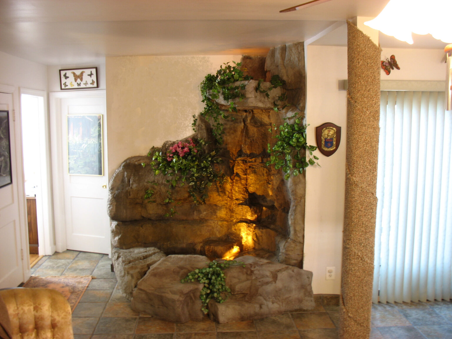
Interior waterfall grotto
Aquatic Artisans Inc. Corner Grotto Waterfall Unit
All work was performed in house by our people. This structure is 100% customizable and can be made lightweight for interior or, heavy duty for exterior installations.
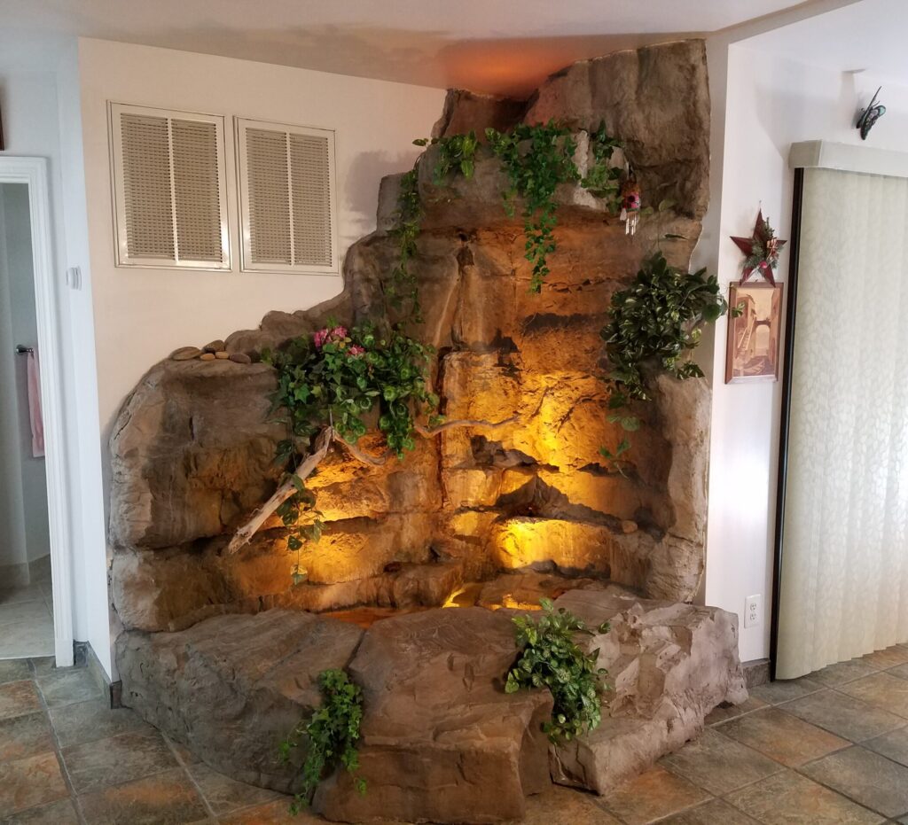
This stunning interior waterfall was crafted using castings molded from natural rock formations, artistically assembled to create a cohesive structure. Spanning 6 feet along the long left-hand wall and 4 feet on the shorter right-hand wall, the top edge of the grotto lid reaches an impressive height of 7 feet, with an additional 11 inches of rock work extending to the ceiling. This top panel can be customized to be larger for taller ceiling heights, making the structure entirely adaptable.
The waterfall can be designed with various configurations, allowing for no water flow or strategically placed outlets to create multiple water features. For instance, the left-hand flower basin or the lower right-hand basin could serve as waterfalls. For a truly dramatic effect, water can cascade from the top grotto, depending on the size of the catch basin.
In this installation, water flows from four distinct locations: #1 comes from just underneath the grotto lid on the left, following the indentation; #2 is 24 inches below and slightly to the right; #3 is positioned 10 inches to the right and 7 inches lower from that sill; and #4 is 12 inches to the left, 6 inches above the waterline, where most of the water is generated.
The size of the pond basin is determined by the available area and whether you wish to include fish. The rocks in front cleverly conceal a pump and UV clarifier, while the transformer and timer for the low-voltage lights are easily accessible through a movable panel on the left side
The interior waterfall corner grotto unit was the brainchild of the pondgod and is his 1st prototype that operated successfully for 15 years without a leak. 0 leaks!
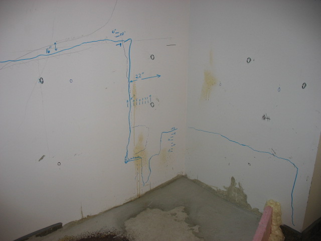
This was a prototype, the 1st 1 so we drew plans on the wall prior attaching castings. The eye-bolts screwed into studs secures all the castings in place.
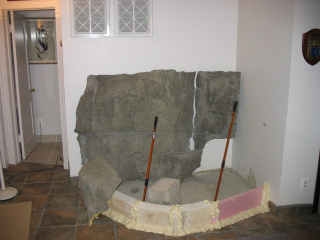
Had to make sure the castings fit in the space and determine the water’s path before applying the water containment system.
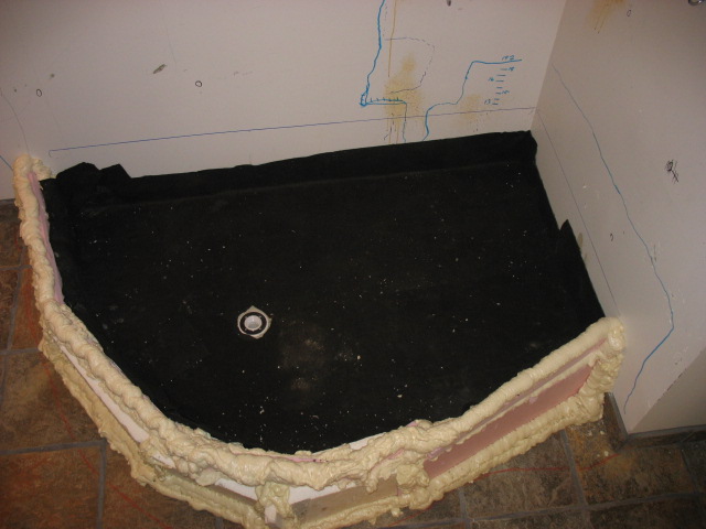
mortar bed was 1st laid to set the grade toward the drain. then covered with a fabric underlayment.
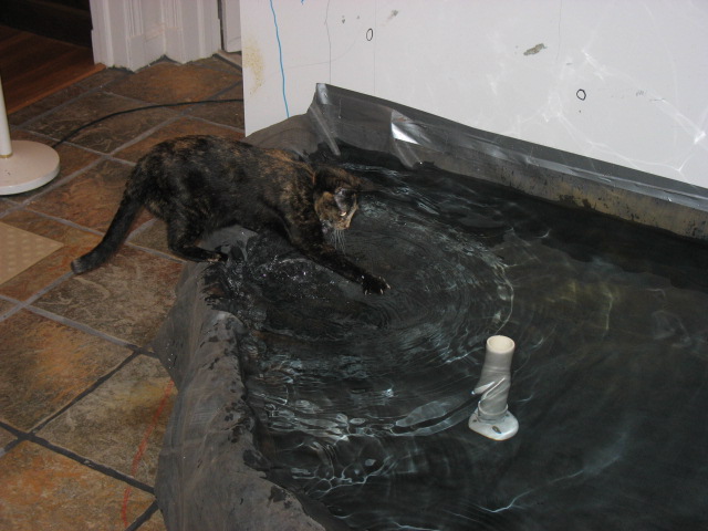
Liner placement to test for leaks, after all it is a prototype but, there were no leaks. No leaks that is until Crookshank’s the cat started splashing the water out. The standpipe guarantees that you won’t accidentally overfill it, lessons learned. When the standpipe is removed, it drains into the basement wash sink for easy cleaning.
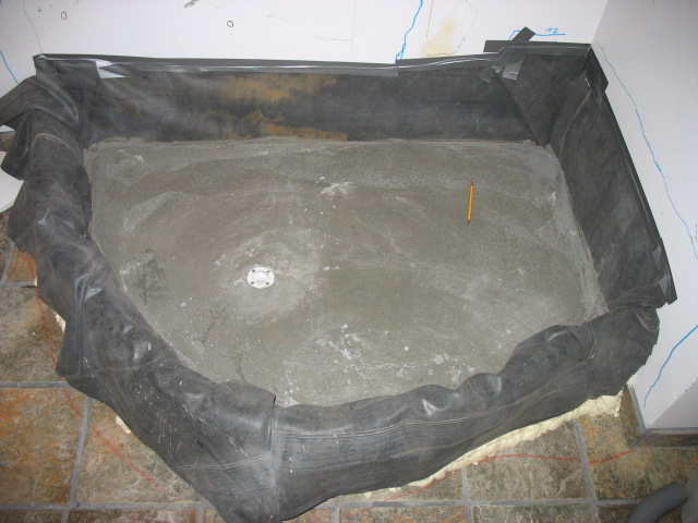
2nd mortar base is for drainage and to protect the liner from the edge of the cement based castings.
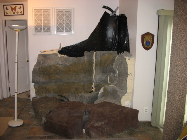
During the creation of our rock castings, we took extra steps to ensure stability by embedding galvanized, vinyl-coated wire into the backside. This wire is then threaded through the eye bolts that secure the castings to the wall studs, providing a robust connection. To enhance the installation, we applied foam to the back of the castings, filling any voids between the wall and the castings. This foam not only adds a secondary water barrier it also provides a a thermal break from the exterior wall to prevent condensation. the foam on the end is to be carved, covered with cement, embedded with rock texture and finish to the wall. Additionally, the black material you see is a commercial grade, urethane based, monolithic, waterproofing membrane.
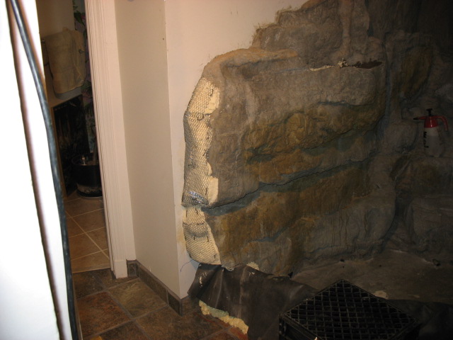
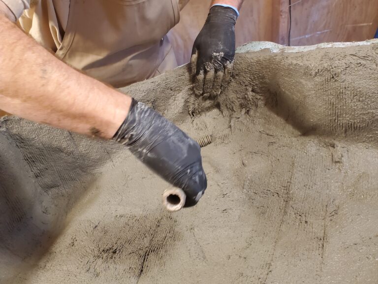
Metal lath is meticulously applied to secure the scratch coat of mortar, ensuring a foundation for the structure. Once the first coat sets, a final layer of mortar is added, hand-carved to match the varying high and low surfaces of the rock. To achieve an authentic appearance, this final coat is then embossed with stone-textured mats, creating a realistic finish that beautifully mimics natural rock.
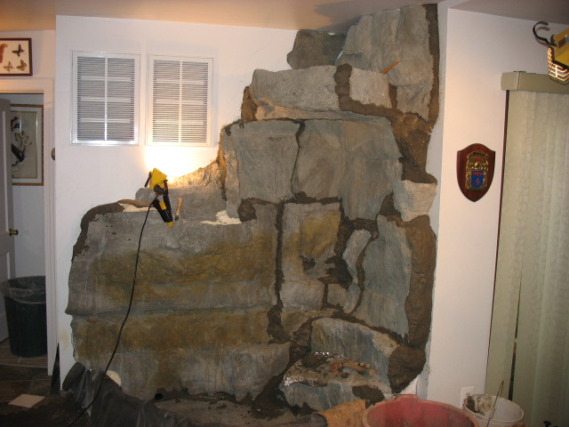
The dark mortar, where we hand-carved and embossed to match the texture of the stone. This meticulous process ensures a seamless integration between the mortar and the rock casting, creating a realistic finish.
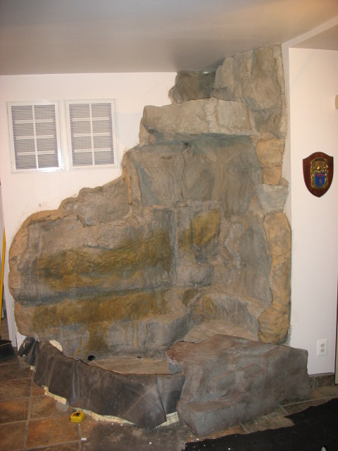
The boulders in front are only temporarily placed, allowing for their removal to create the production mold of the finished project. While we experimented with some color early on, we ultimately found no pressing need to color the rest of the structure. Inside the house, the lighting complements the natural cement tones beautifully, making the existing colors appear just right.
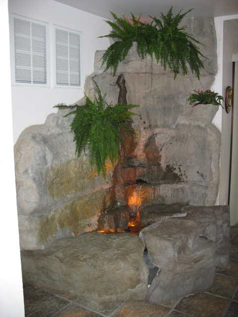
We tested the waterfall thoroughly before creating the production mold. Fortunately, no significant adjustments were needed, aside from fine-tuning valves to control the water volume to the various outlets. Designing the water flow is crucial to prevent any splash outside the containment area, especially indoors, as this is the number one failure for both internal and external water features—water can be costly and the message it makes is unacceptable. The majority of the flow originates from 6 inches above the water line, with lesser amounts cascading from higher outlets. By adjusting the flow rate, we ensure that the water remains in contact with the surface of the structure, effectively eliminating any unwanted splash.
Creating a production mold
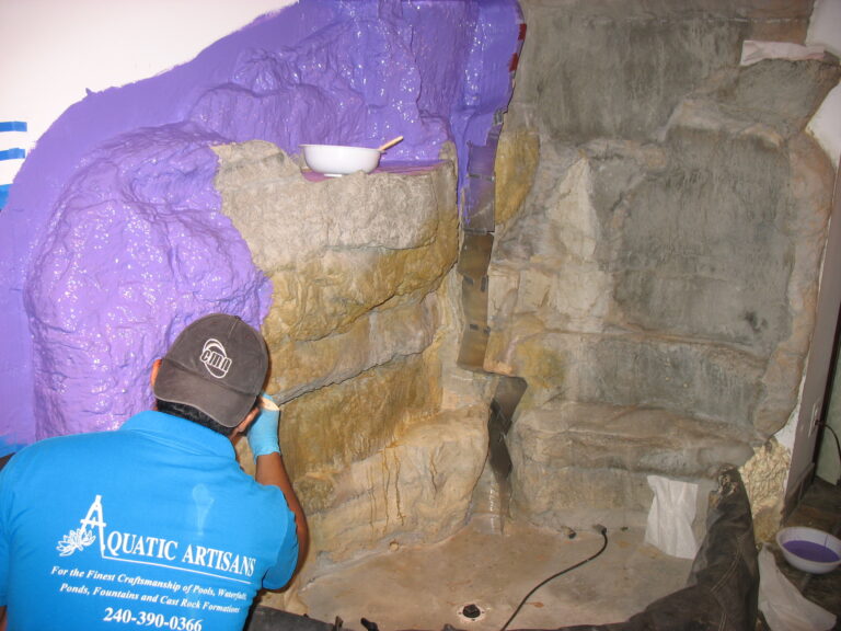
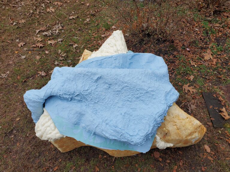
Here were using silicone to create a glove mold. The glove mold captures all the texture and details like cracks and crevices on the rock. The next mold is a hard-shell called, the mother mold that, captures the shape.
for the unit
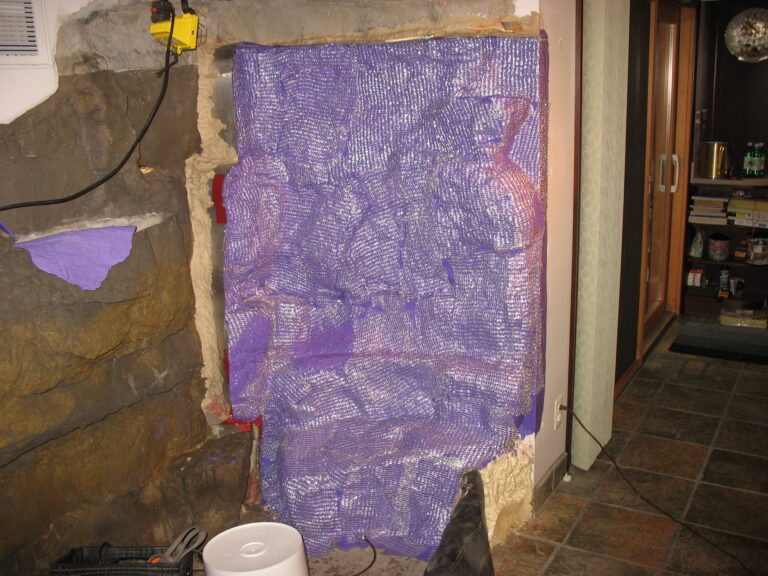
Silicone, while flexible, offers very little tear resistance. To enhance durability, we embed a silver mesh between the coats of silicone, creating a ripstop effect.
Now, competitors, are you taking all this information in? Is there anything we can do to help you elevate your game—other than trying to take credit by showcasing our work on your websites? You all know who you are. Posers!
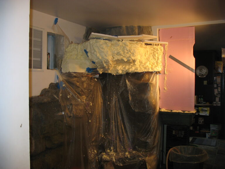
Here, we’re using a 2 lb. foam to create the mother mold for the grotto overhang. While it can be messy, it’s much less odorous than our default mother mold material, fiberglass. We prioritized speed and minimizing odors to quickly get the house and waterfall back in operation. The foam can be easily carved and shaped, allowing us to cover it with fiberglass afterward for added durability
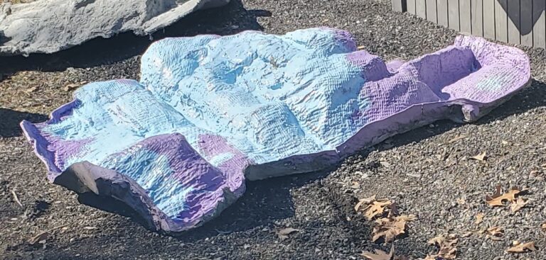
One key advantage of using silicone is its repairability. If the mold is damaged—say, by a mouse chewing through it or from a crack due to improper storage—repairs can be made without the risk of delamination, unlike with latex. While latex offers greater tensile strength and tear resistance, it tends to stretch, once cross-linked/cured it will delaminate and, being a natural material, deteriorates over time.
This skin could not be salvaged, so we had to start from scratch. When creating a mold, it’s essential to maintain a catalog of all the masters or copies of each item. Fortunately, since we had a copy of this one, we were able to produce a new skin. The upper picture shows an old skin that has been repaired, and from that, we created another copy to use for the new skin
The next step is casting into the mold
We are casting a special mix recipe that is very strong and lightweight called, GFRC, Glass fiber reinforced concrete. 1st a base coat without fiberglass is sprayed into the mold that, will pick up all the detail from the rubber mold.
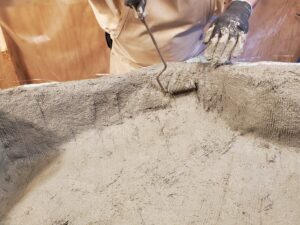
The next step involves adding a specially formulated fiberglass to the mix to strengthen the face coat. Here, we’re rolling the fiberglass into the cement mixture, ensuring that any air pockets are removed. Depending on the required strength, a third or fourth coat may be necessary. Typically, three coats will yield a thickness of about three-quarters of an inch, achieving a strength of 7,000 psi
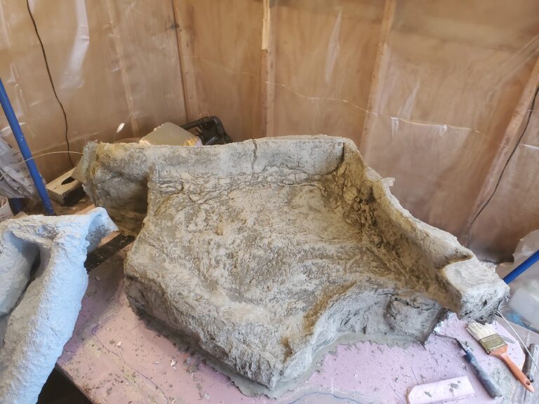
Here is the grotto lid casting fresh out of the mold, showcasing the face side. While it may appear thicker than it is, it will need to be trimmed for the final finish.
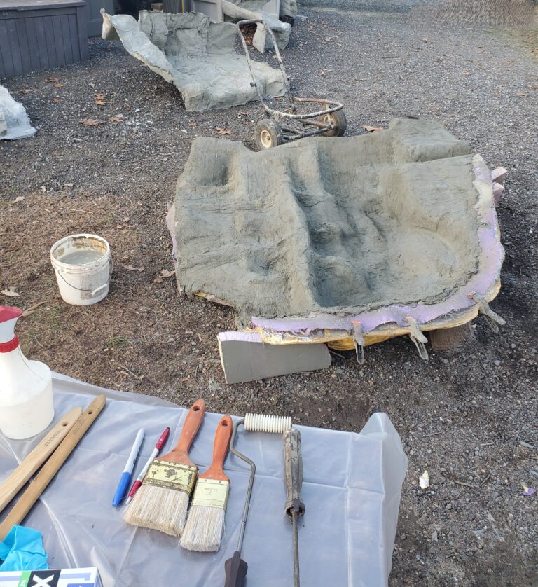
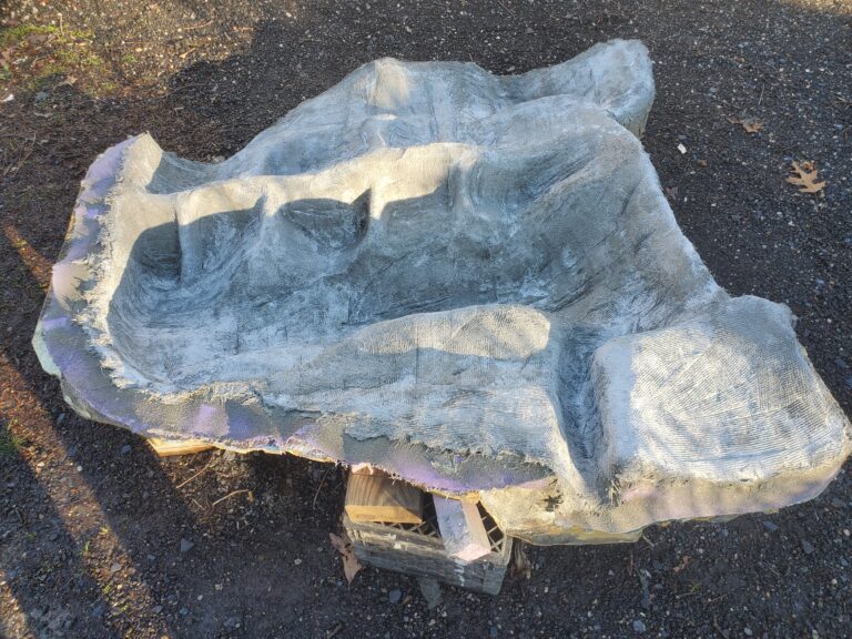
This is the longwall casting of the corner waterfall unit. It was designed to be as lightweight as possible for indoor use, featuring just one face coat and one fiberglass coat, and weighing in at less than 100 lbs. Note the four hand-molded support struts, which are specifically designed to reinforce this stress point. The top of the casting is facing you, while the bottom is at the top of your screen. Once the casting has cured, the backside will be sprayed with high-density 4 lb. foam, which has a hardness comparable to balsa wood
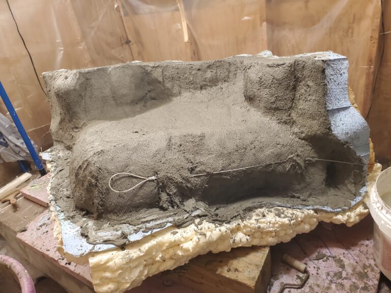
This view is from the unseen, inside of the grotto lid. demonstrating the positioning and installation of stainless steel support cables. the loop in the cable is permanently embedded in the concrete so that it will not pull out
We have support cables embedded in the GFRC matrix left, right and, center
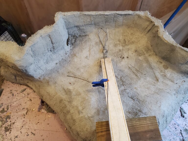
We install three stainless steel support cables, each with a breaking strength of 800 lbs. These support cables are then securely attached to eyebolts anchored into the wall studs
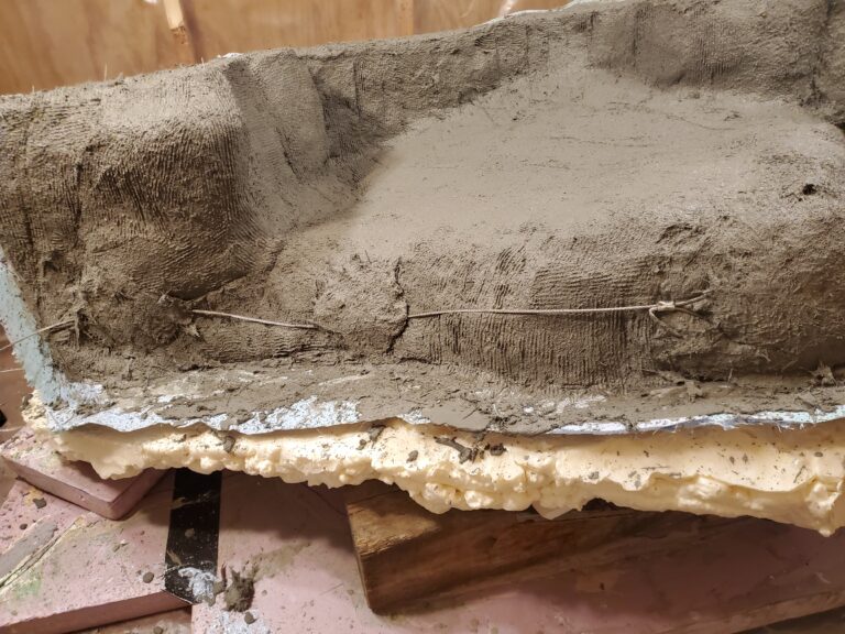
The original waterfall unit did not have these cables installed, and while there were no alarms, we deemed it prudent to enhance safety. The original prototype successfully supported 30 pounds of plants and soil without any issues
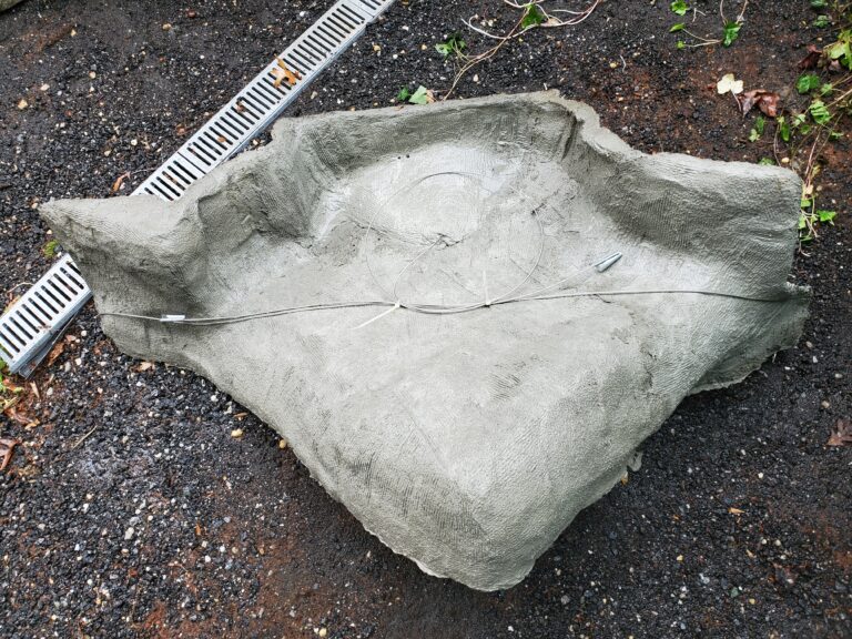
Here the cables are fully embedded into the GFRC matrix @7000 psi.
The original prototype did not have support cables.
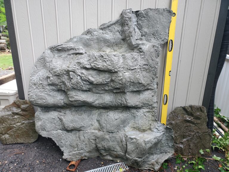
All three pieces cover a corner area measuring 6′ x 4′ x 7′ tall. We stopped at 7 feet to accommodate varying ceiling heights, allowing for additional panel pieces to be added as needed to match your specific ceiling height.
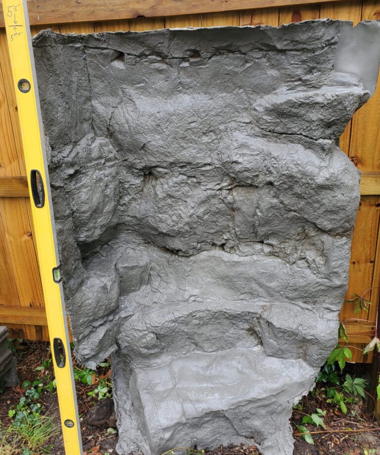
The mark on the level is at 5 feet.
